Page 1 of 2
Electronics question
Posted: Mon May 17, 2010 2:28 pm
by Metalfab_101
This is loosely MS related so I figured I am OK to put it in here.
My problem comes from using the factory ECU harness for the MS install. I have a ECU connector from a dead ECU and have used that to make an adapter loom from between the stock loom and the MS DB37. Where I ran into trouble was with the circuitry for the main power relay. The relay's coil is switched on both the positive AND negative side, the positive through the ignition switch, and the negative side through the ECU. When the ECU is removed then that part of the circuit is removed, and the main relay does not turn on. So I have to come up with some way of switching the relay's coil to ground, using a +12v input.
I did some googling and read some on using transistors as a switch. Like this:
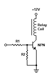
Now if my understanding is correct R1 is connected to the base, the emitted goes to GND and the relay coil is connected to the collector. When a voltage is put to the base that allows current to flow from the collector to the emitter. The relay coil already has +12v on one side so it's effectively grounding the other side.
Re: Electronics question
Posted: Mon May 17, 2010 3:32 pm
by long283
That circuit will work fine.
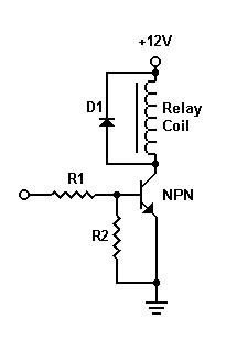
If you are switching a few amps or more you may want to add a diode (eg. 1N4004) across the relay to protect the transistor from an emf spike when the relay is switched off. Connect the cathode to the positive (+12V) side of the relay and the anode to the transistor side.
Here's a reference if a picture helps
http://en.wikipedia.org/wiki/Flyback_diode
Re: Electronics question
Posted: Mon May 17, 2010 6:59 pm
by devojet
Let me know if I have read your post correctly. The 12V side of the relay is switched from the ingition, and the ground side is switched through the Factory ecu. I assume this relay feeds power to the MS, injectors coils etc.
If that is correct, then why not just ground the ground side and rely on the ignition switch to control the relay? Thats how a main relay would be done in a normal MS install.
Otherwise I agree with long283.
Cheers
Daniel.
Re: Electronics question
Posted: Mon May 17, 2010 7:30 pm
by Metalfab_101
devojet wrote:Let me know if I have read your post correctly. The 12V side of the relay is switched from the ingition, and the ground side is switched through the Factory ecu. I assume this relay feeds power to the MS, injectors coils etc.
If that is correct, then why not just ground the ground side and rely on the ignition switch to control the relay? Thats how a main relay would be done in a normal MS install.
Otherwise I agree with long283.
Cheers
Daniel.
Actually my description is not quite right because I tried that and even with the ignition off when I ground the -ve side of the relay coil it turns on, so the relay must have constant 12v to it.
The EMF spike was going to be my next question, thanks for mentioning that!!!
Re: Electronics question
Posted: Mon May 17, 2010 7:41 pm
by Metalfab_101
I modified the diagram, with the diode as suggested by long283.
I'll set this up on a proto board and see how it goes. Thanks again!
Re: Electronics question
Posted: Tue May 18, 2010 2:33 pm
by long283
I remember my dad had a problem with a commodore v6 in a rodeo. He tried changing the relay switching but it also had a switch that opened when the oil-press went too low. It didn't want to switch off while the engine had oil-press after the wiring mod.

That updated diagram is correct.
Another way to protect the transistor is to use a ~22V zener. Connect the cathode to the transistor on the negative side of the coil and the anode to ground. Similar to the wiring in the MS for the fuel-pump, Idle-air Solenoid circuits.
Re: Electronics question
Posted: Wed May 19, 2010 4:00 am
by Metalfab_101
I checked the relay's coil resistance and it's 69.6 ohms. So I calculate the current draw to be about 170mA @ 12v. So a PN2222A should handle that current no problems.
Right?

Re: Electronics question
Posted: Wed May 19, 2010 6:07 pm
by devojet
Yeah the PN2222A should be fine. The data sheet says it can handle 1A max.
Cheers
Daniel.
Re: Electronics question
Posted: Thu May 20, 2010 5:13 am
by Metalfab_101
Thanks Daniel. I'm trying ti figure out my resistor values now, and need the Hfe. I look on the datasheet but there's half a dozen values. I think 100 is the closest minimum value? As it says 10v and 150mA. What Hfe figure should I use?
EDIT: Added datasheet as attachment
Re: Electronics question
Posted: Thu May 20, 2010 4:18 pm
by long283
The way you will be using the transistor is more like a switch. You simply want it to turn on or off, like a digital circuit. I believe you should go for maximium gain to keep the gate saturated, as long as the voltage divider keeps the gate below its maximum voltage.
Someone please correct me if I'm wrong.