Help please
-
windsorsmith
Help please
I have built the stim kit 2.2 & have got to step 23 on the PCB3.0 instructions. I don't seem to be getting the right voltage readings from the pins & earths from
DB-37. I am getting the right readings from voltage regulator U5. I may be misreading or mis-understanding the instructions I am new to this.
I was enjoying the building process, but I don't want to go any further untill I know it's right.
I will be grateful for any help any one can give.
Thanks in advance.
Grant.
Re: Help please
Welcome to the world of MegaSquirt .
If you have chosen a MS system then I'm sure you have a basic knowledge of electronics and by the time you have finished you will have learnt a lot more.
What voltages are you getting on those pins?
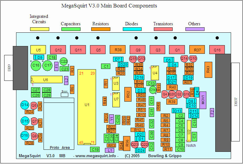
The pins you are checking are on the 40-pin socket that the processor or mother board plugs into not the DB-37
-
windsorsmith
Re: Help please
Thanks for the help. In the instructions are confusing,it says to plug the stim into DB37 & then it says to check the voltage on the empty socket.
Any way I am getting no voltage from all the pins they say to test on the empty socket.
I have checked all components on the stim & I can't see any mistakes or bad solder joints.
When it"s plugged into the mother board I get about 3.36 volts on each pin they say to check.
It looks like I am the only one who started this badly, I don"t know what to do next.
Thanks again.
Grant.
Re: Help please
The first thing would be to make sure you have a good plug pack powering your Stim. The 9v battery does not last long enough for testing and a 12VDC plug pack will do the job much better. Yes, you can use up to 12Volts.
That is correct, power the MS with your Stim plugged into the DB-37 connector and measure the voltages on the empty socket.windsorsmith wrote:In the instructions are confusing,it says to plug the stim into DB37 & then it says to check the voltage on the empty socket.
To measure the voltages connect the negative (black) lead of your multimeter on pins 2, 19 or 32 and connect the positive (red) lead of your multi-meter on pins 1, 20 or 31.
Any of those commbinations should give a reading of ~ +5VDC.
One quick question, are you using a MegaStim or a JimStim? (don't worry, either one will work the same for the testing)
-
windsorsmith
Re: Help please
I am now using a 12 volt supply. My stim is a Megastim V2.21.
Unfortunatly I still don't understand when the megastim is plugged into DB-37 the sockets are not empty.
What am I not understanding?(I feel dumb) sorry to keep bothering YOU.
I really want to move on & complete the board.
Thanks Grant.
Re: Help please
The MegaStim plugs into the DB-37 and powers the unit.
The sockets that you will be testing are the two 20-pin rows that form the 40-pin socket for U1 on the components diagram. That is where the daughter board plugs in, leave the daughter board out to test the voltages.

-
windsorsmith
Re: Help please
I finally understand, I didn't know the proper sockets to test. I've just done it & I'm getting about 4.94 volts on all sockets.
I hope that's enough. I might try it with another meter this afternoon & continue on,I feel much better now.
Thanks.