Page 1 of 3
36-1 Crank Wheels
Posted: Mon May 17, 2010 4:13 am
by long283
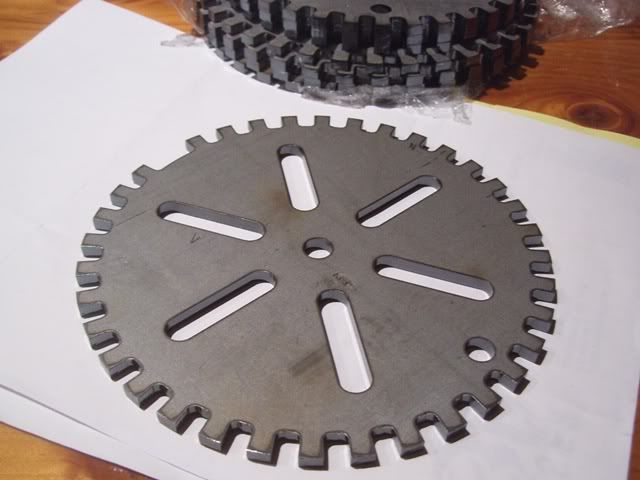
I have put in a couple of drawings to get a quote for laser cutting.
They will be made out of 3mm mild-steel. One is a 6inch wheel (to suit holden straight sixes). And a 7inch wheel ( to suit 6 3/4" to 7" balancers, eg. chev).
If anyone is interested let me know in the next couple of days. I am based in Sydney.
I can email the .dxf or .dwg files but double check if the dimensions are correct/suitable for your application.
Or if anyone has any comments on the design lets hear them.
Re: 36-1 Crank Wheels
Posted: Mon May 17, 2010 6:15 pm
by wagon
If only.... I've had a cad drawing for 36-1 wheels for a few years now ; it could have saved you some work.
Also, some vr sensors don't work as well will thinner wheels - thicker seems to give a higher output voltage. Mine is 5mm, works very well.
Re: 36-1 Crank Wheels
Posted: Mon May 17, 2010 7:48 pm
by Metalfab_101
wagon wrote:If only.... I've had a cad drawing for 36-1 wheels for a few years now ; it could have saved you some work.
Also, some vr sensors don't work as well will thinner wheels - thicker seems to give a higher output voltage. Mine is 5mm, works very well.
Just out of interest, could you use hall instead of a VR as the pickup with one of these wheels?
Re: 36-1 Crank Wheels
Posted: Tue May 18, 2010 2:27 pm
by long283
The wheels are going to cost between $20-25. I think I will get four of each. I plan on using two of the large and one of the small ones, the rest are for spares or future projects. Don't worry, I use CAD at work and it doesn't take me long to draw/modify a drawing.
I was thinking of using a gear tooth sensor (hall-effect) like this one
http://au.farnell.com/allegro-microsyst ... tt=1278528. A workmate used one with an electric motor turning to 24000rpm, using 3mm wide tooth, 3mm gaps, 10-teeth on the wheel. The specs say they will handle up to 8kHz.
Re: 36-1 Crank Wheels
Posted: Thu May 20, 2010 4:13 pm
by long283
Ok. Wheels are being made.
I changed the thickness to 5mm to be on the safe side, plus that gives me the option of using a VR sensor instead.

Re: 36-1 Crank Wheels
Posted: Fri May 21, 2010 3:51 am
by wagon
Metalfab_101 wrote:wagon wrote:If only.... I've had a cad drawing for 36-1 wheels for a few years now ; it could have saved you some work.
Also, some vr sensors don't work as well will thinner wheels - thicker seems to give a higher output voltage. Mine is 5mm, works very well.
Just out of interest, could you use hall instead of a VR as the pickup with one of these wheels?
Can't see any reason.. I think Jaycar sell an 'automotive' style hall sensor with wires and such reason to go. You'd need a thin wheel to pass through the gap, it's only little.
Re: 36-1 Crank Wheels
Posted: Wed Jun 02, 2010 12:43 am
by long283
Got the 36-1 wheels back. They look quite neat, very happy with them.
I'll order the sensors and some other electronics for the semi-sequential conversion either tonight or tomorrow.
I've got the car running with the MS2 Extra code now and have modified a second MS2 to run 4 x coil packs & 4 x ignition channels. I just need to build the output circuits.
I'll post some more info when I get a bit more done.
Re: 36-1 Crank Wheels
Posted: Sat Jul 03, 2010 9:58 pm
by aphesis
That came out well.
Just a question, how do you centre it on the balancer and is there a chance of it moving once it is bolted down?
Do you have any pics of the motor, interested in placement of the sensor.
Thanks
Re: 36-1 Crank Wheels
Posted: Mon Jul 05, 2010 7:42 pm
by long283
The balancer has three 3/8UNF bolts to hold the v-belt pulley on. I was going to change the crank-balancer bolt to a stud to centralise the 36-1 wheels but haven't found what I want for that at the moment. The three bolts should hold the 36-1 wheel fairly central with only a small amount of adjustment needed.
I've also welded a large nut on the front of a 36-1 wheel and will be trying that out. The nut will make it a lot easier to turn the motor over to adjust the timing or rocker clearance. I used a TIG welder to tack it in four places without warping it much.
The Chev engines have two 3/8"UNC bolt holes on the front block just above the oil pan rail. Mounting the sensor using these holes will place the sensor inside the v-belt loop so that the fan-belt can still be removed without moving the sensor.
I'll try to get some photos up shortly.
Re: 36-1 Crank Wheels
Posted: Sat Jul 10, 2010 11:56 pm
by long283
Here's a picture of the 36-1 wheel installed,
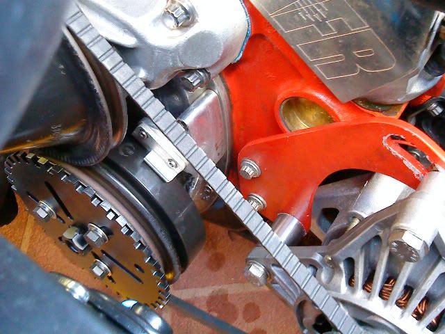
The three bolts keep the wheel quite centralised. I made up three aluminium spacers to go behind and stop the wheel pulling into the pulley dish.
In the middle of the picture you can see the two bolt holes, currently being used for the alternator bracket, that will hold the hall-sensor or VR-sensor. I hope to get that done this week and start using the C.A.S. because the distributor keeps coming loose at the moment.